Chapter 11: Installation & Debugging
Step-by-step installation procedures, configuration commissioning, and systematic debugging for wireless security systems
Proper installation and commissioning are the foundation of a reliable wireless security system. Even the best-designed system will fail to meet its security and performance objectives if the physical installation is incorrect or the configuration is incomplete. This chapter provides a structured, step-by-step guide for the installation of all wireless security components, followed by a systematic commissioning and debugging procedure that ensures every security function is verified before handover.
11.1 Installation Requirements
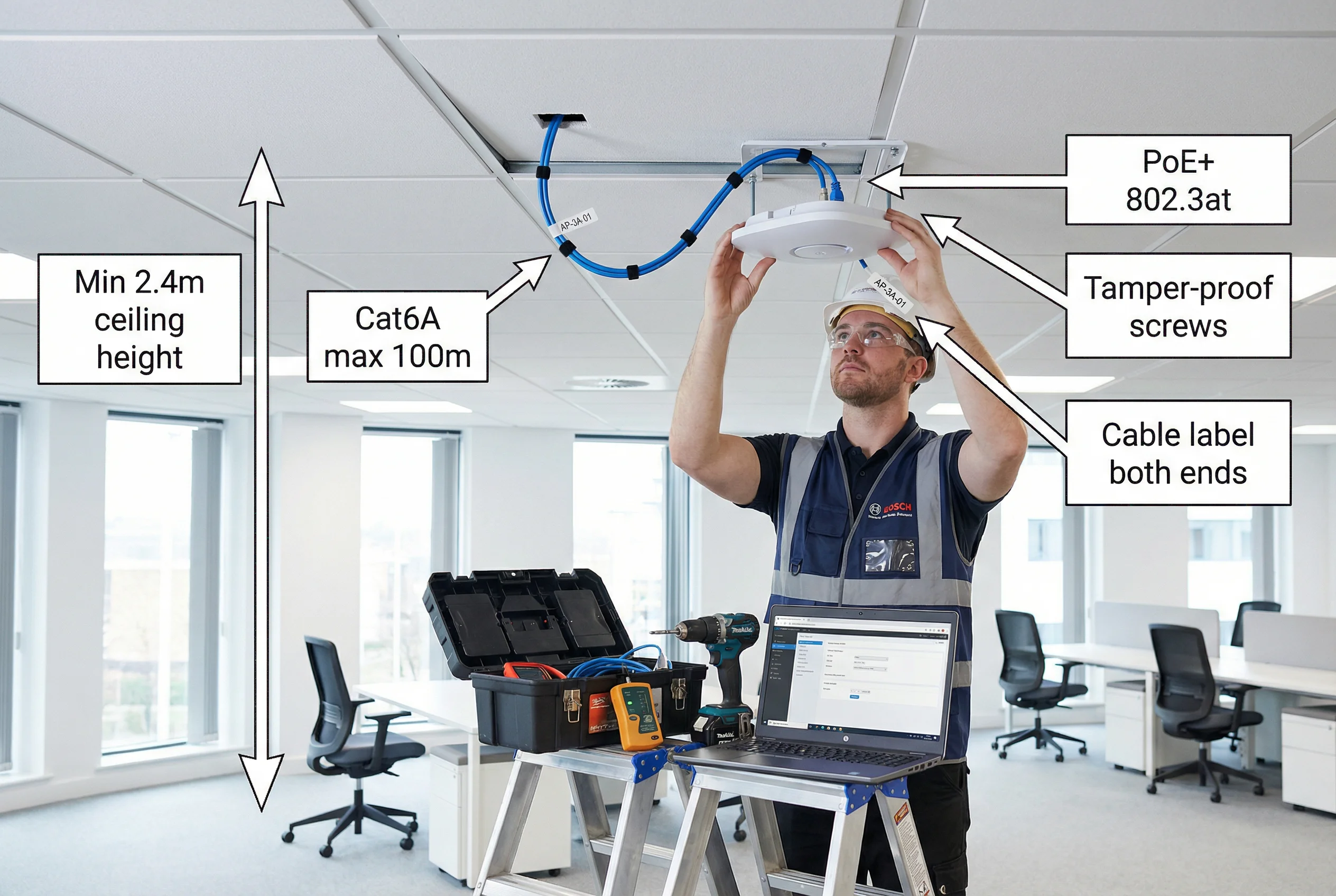
Before any physical installation begins, the site must be prepared and all pre-installation requirements verified. The following photograph illustrates the correct installation environment, technique, and required annotations for a compliant enterprise AP installation.
| Installation Requirement | Specification | Rationale |
|---|---|---|
| Minimum Ceiling Height | 2.4m (indoor AP), 3.0m preferred | Ensures adequate coverage radius and prevents physical tampering |
| Cable Standard | Cat6A STP, LSZH jacket, max 100m per run | Supports PoE++ and 10GbE uplink; LSZH for fire safety |
| PoE Standard | IEEE 802.3at (PoE+, 30W) minimum; 802.3bt (PoE++, 60W) for Wi-Fi 6E | Adequate power for dual-radio operation and integrated BLE/WIPS |
| Mounting Hardware | Tamper-proof Torx screws, security cable lock (high-risk areas) | Prevents physical theft and unauthorized AP replacement |
| Cable Labeling | Wrap-around label at both ends: AP-[Building]-[Floor]-[ID] | Enables rapid fault isolation and asset tracking |
| Clearance from Obstructions | Minimum 300mm in all directions from AP antenna | Prevents RF absorption and multipath interference |
| Distance from Interference Sources | Minimum 1m from microwave ovens, 2m from fluorescent ballasts | Reduces co-channel interference and noise floor elevation |
| Outdoor AP Enclosure | IP67 minimum, UV-resistant, -40°C to +65°C operating range | Environmental protection for outdoor deployments |
11.2 Installation Sequence
The following ordered procedure must be followed for all wireless security component installations. Deviating from this sequence — particularly by attempting to configure software before physical installation is complete — is a common cause of commissioning failures.
-
1Pre-Installation Site Survey VerificationVerify that the physical site matches the design drawings. Confirm ceiling height, cable routing paths, and power availability at each AP location. Document any deviations from the design and obtain approval before proceeding.
-
2Infrastructure PreparationInstall cable conduit, cable trays, and junction boxes. Pull Cat6A cable runs from each AP location to the IDF/MDF. Test each cable run with a cable tester before termination. Terminate cables at patch panels and wall plates.
-
3PoE Switch Installation and ConfigurationRack-mount PoE switches in IDF cabinets. Configure VLANs, 802.1X port authentication (for AP uplink ports), and PoE power class limits. Verify PoE budget does not exceed switch capacity. Connect uplinks to core/distribution switches.
-
4WLAN Controller and RADIUS Server DeploymentDeploy WLAN Controller (hardware or virtual) and RADIUS servers in the data center. Configure RADIUS with AD/LDAP integration, EAP method, and certificate validation. Configure WLAN Controller with AP groups, SSID profiles, and VLAN mappings. Test RADIUS authentication before deploying APs.
-
5Access Point Physical InstallationMount AP brackets at approved locations. Route Cat6A cable through conduit to AP location. Connect cable to AP, verify PoE LED indicates correct power class. Secure AP to bracket with tamper-proof screws. Affix asset label. Verify AP joins controller (LED or controller dashboard).
-
6SSID and Security Policy ConfigurationConfigure SSIDs on controller: WPA3-Enterprise with PMF mandatory for corporate SSID; WPA3-SAE for IoT; WPA3-Personal for guest with captive portal. Apply VLAN assignments, client isolation, and rate limiting policies. Enable WIPS on all APs.
-
7RF OptimizationRun automatic RF optimization on the controller (RRM/ARM). Verify channel assignments avoid co-channel interference. Adjust transmit power to achieve target RSSI at coverage boundaries. Verify 15–25% overlap between adjacent APs for seamless roaming.
-
8Security Validation and Acceptance TestingPerform all acceptance tests per Chapter 10. Verify 802.1X authentication, VLAN assignment, WIPS detection, and guest isolation. Conduct walk-test with site survey tool to generate coverage heatmap. Document all test results.
11.3 Common Issues and Debugging
| Symptom | Probable Cause | Diagnostic Steps | Resolution |
|---|---|---|---|
| AP not joining controller | VLAN misconfiguration, DHCP issue, firewall blocking CAPWAP | Check AP DHCP lease; verify CAPWAP ports (UDP 5246/5247) open; check AP console log | Correct VLAN tagging on switch port; open CAPWAP in firewall; verify DHCP scope |
| 802.1X authentication failing | Certificate mismatch, RADIUS unreachable, wrong EAP method | Check RADIUS logs for reject reason; verify cert chain; test RADIUS connectivity from AP | Re-issue certificate; correct RADIUS shared secret; match EAP method on client and server |
| Client in wrong VLAN | RADIUS policy misconfiguration, AD group membership issue | Check RADIUS access-accept attributes; verify AD group membership; check VLAN mapping table | Correct RADIUS policy; update AD group; verify VLAN-to-group mapping on controller |
| Poor coverage / low RSSI | AP placement incorrect, transmit power too low, physical obstruction | Run site survey; check AP transmit power setting; verify no new obstructions since survey | Relocate AP; increase transmit power; add AP to fill coverage gap |
| Slow roaming / dropped calls | 802.11r/k/v not enabled, excessive AP overlap, sticky client | Verify 802.11r enabled on SSID; check overlap percentage; monitor client roam events | Enable 802.11r/k/v; adjust AP power to reduce overlap; enable aggressive roaming on controller |
| PoE power insufficient | Switch budget exceeded, wrong PoE class negotiated | Check switch PoE budget dashboard; verify AP PoE class in controller; check cable quality | Redistribute APs across switches; upgrade to higher-budget switch; replace cable if Cat5e |