Chapter 4: Architecture Design
Typical system topology, device wiring, VLAN segmentation, and redundancy design for enterprise wireless security
4.1 Typical System Topology
The enterprise wireless security system follows a hierarchical three-tier switching architecture combined with a dedicated security services plane. The topology separates the data forwarding path (access → distribution → core) from the security services path (authentication, authorization, monitoring), ensuring that security infrastructure failures do not directly impact data forwarding, and vice versa. Four VRFs — Corp (VLAN 10), IoT (VLAN 20), Guest (VLAN 30), and Mgmt (VLAN 99) — are maintained from the access layer through the core, with firewall enforcement at zone boundaries.
The core firewall HA pair sits at the network perimeter, handling internet-bound traffic and enforcing zone policies between VRFs. The core switch HA pair provides high-bandwidth, low-latency switching between distribution zones and the security services plane. Distribution switches are logically separated by zone, reducing the blast radius of any single distribution failure. PoE access switches provide 802.3at/bt power to APs and enforce 802.1X port authentication for wired devices. The security services plane — WLAN Controller, RADIUS Cluster, PKI, NAC, and SIEM — is connected to the management VLAN with dedicated uplinks to the core.
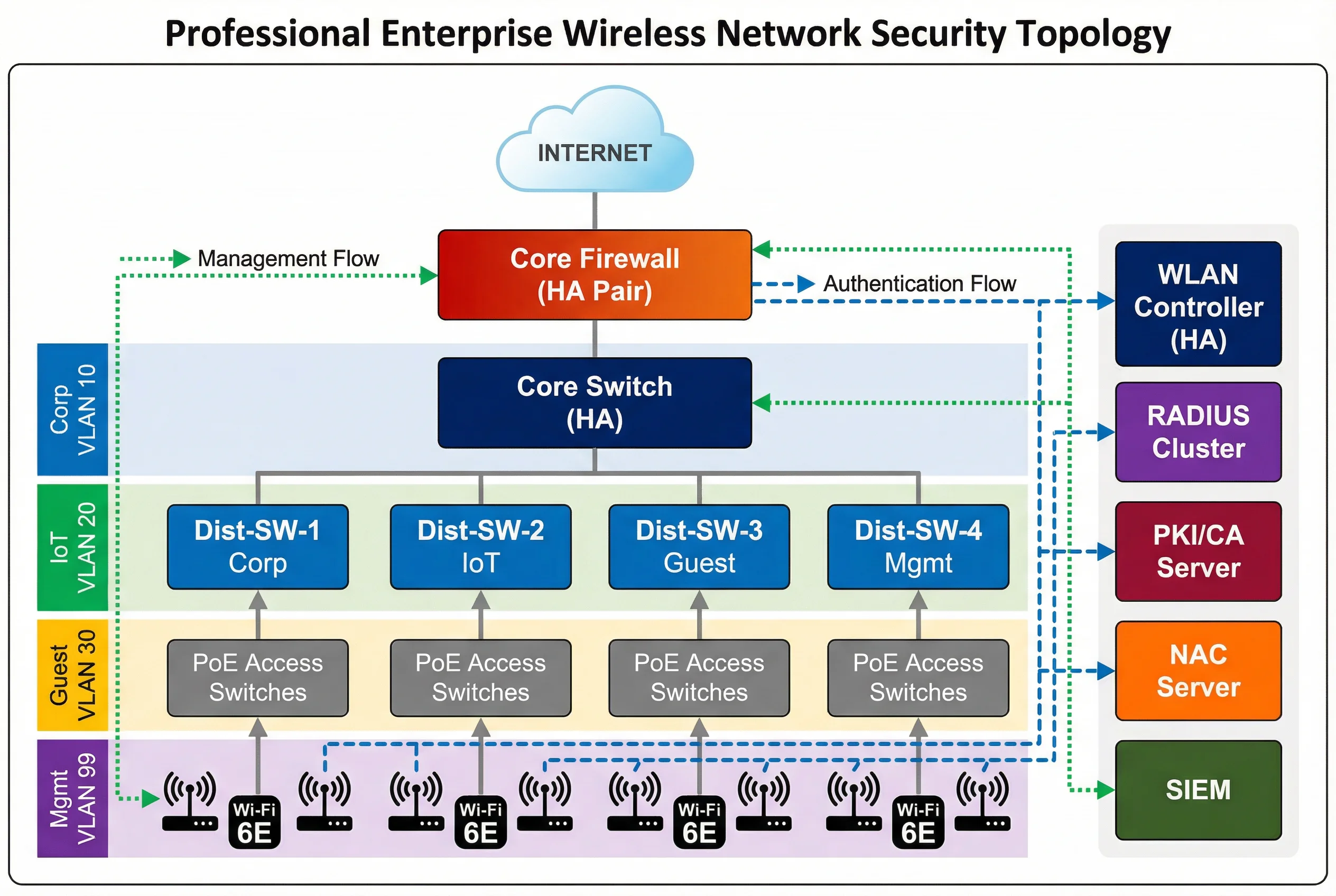
Traffic Flow Descriptions
| Flow Type | Path | Protocol | Notes |
|---|---|---|---|
| Authentication Flow | AP → Controller → RADIUS → IdP/PKI | CAPWAP/TLS, RADIUS UDP 1812 | Dashed blue arrows; must complete before data flow permitted |
| Data Flow (Corp) | AP → PoE Switch → Dist-SW-1 → Core → Firewall → Internet/DC | 802.1Q VLAN 10, encrypted | Solid gray; firewall enforces zone policy |
| Data Flow (Guest) | AP → PoE Switch → Dist-SW-3 → Core → Firewall → Internet only | 802.1Q VLAN 30 | No RFC1918 reachability; DNS filtering applied |
| Management Flow | SIEM/NMS → Mgmt Switch → All devices | SNMP, Syslog, SSH, NTP | Dotted green; OOB management preferred |
| WIPS Telemetry | AP/RF Sensor → Controller → SIEM | CAPWAP, Syslog | Continuous RF monitoring data stream |
4.2 VLAN and Zone Design
Network segmentation is implemented through a combination of 802.1Q VLANs at the access and distribution layers, and VRF instances at the core and firewall. This dual-layer segmentation ensures that even if a VLAN misconfiguration occurs at the access layer, the VRF boundary at the core prevents cross-zone traffic from reaching unintended destinations. The firewall enforces explicit permit rules between zones, with an implicit deny-all default policy.
| Zone | VLAN ID | Subnet | Users/Devices | Internet | Corp Access | IoT Access |
|---|---|---|---|---|---|---|
| Corp | 10 | 10.10.0.0/22 | Managed staff, MDM devices | Yes (filtered) | Full | No |
| IoT | 20 | 10.20.0.0/22 | Sensors, cameras, building systems | Allowlist only | No | Allowlist |
| Guest | 30 | 10.30.0.0/22 | Visitors, BYOD, contractors | Yes (DNS filtered) | No | No |
| Mgmt | 99 | 10.99.0.0/24 | Network devices, servers | No | Admin only | No |
Tunnel-Type=VLAN, Tunnel-Medium-Type=802, and Tunnel-Private-Group-ID=<VLAN-ID> attributes. The AP and switch enforce the assigned VLAN for that specific client session, enabling multiple VLANs to coexist on a single AP or switch port.
4.3 Redundancy and High Availability Design
Enterprise wireless security systems must maintain continuous operation despite hardware failures, software faults, and planned maintenance windows. Redundancy is implemented at every critical layer: controller HA, RADIUS cluster, core switch HA, firewall HA, and dual uplinks from APs to distribution. The redundancy design targets a Recovery Time Objective (RTO) of less than 30 seconds for controller failover and less than 5 seconds for RADIUS failover.
| Component | Redundancy Model | Failover Time | State Sync | Notes |
|---|---|---|---|---|
| WLAN Controller | Active-Standby HA | <30s | Full session state | APs rejoin standby automatically |
| RADIUS Server | Active-Active cluster (VIP) | <5s | Session database replicated | Load balanced; failover transparent |
| Core Switch | VSS/HA stack | <1s | Control plane sync | Single logical switch to upstream |
| Firewall | Active-Passive HA | <3s | Session table sync | Stateful failover preserves sessions |
| PKI/CA | Primary + Offline backup | Manual (RTO <4h) | CRL/OCSP cached | OCSP caching reduces dependency |
| AP Uplinks | Dual-home to two PoE switches | <1s (STP/LACP) | N/A | Prevents single switch failure from dropping APs |
4.4 Equipment Rack and Device Wiring
Physical equipment is organized across three rack groups: the WLAN and Security rack (WLAN Controller, RADIUS, PKI), the Core and Distribution rack (core switch, distribution switches, PoE access switches), and the Edge and Management rack (firewall HA pair, management switch). Cable management follows color-coding conventions to facilitate troubleshooting and maintenance. All inter-rack connections use fiber SFP+ modules for high bandwidth and noise immunity.
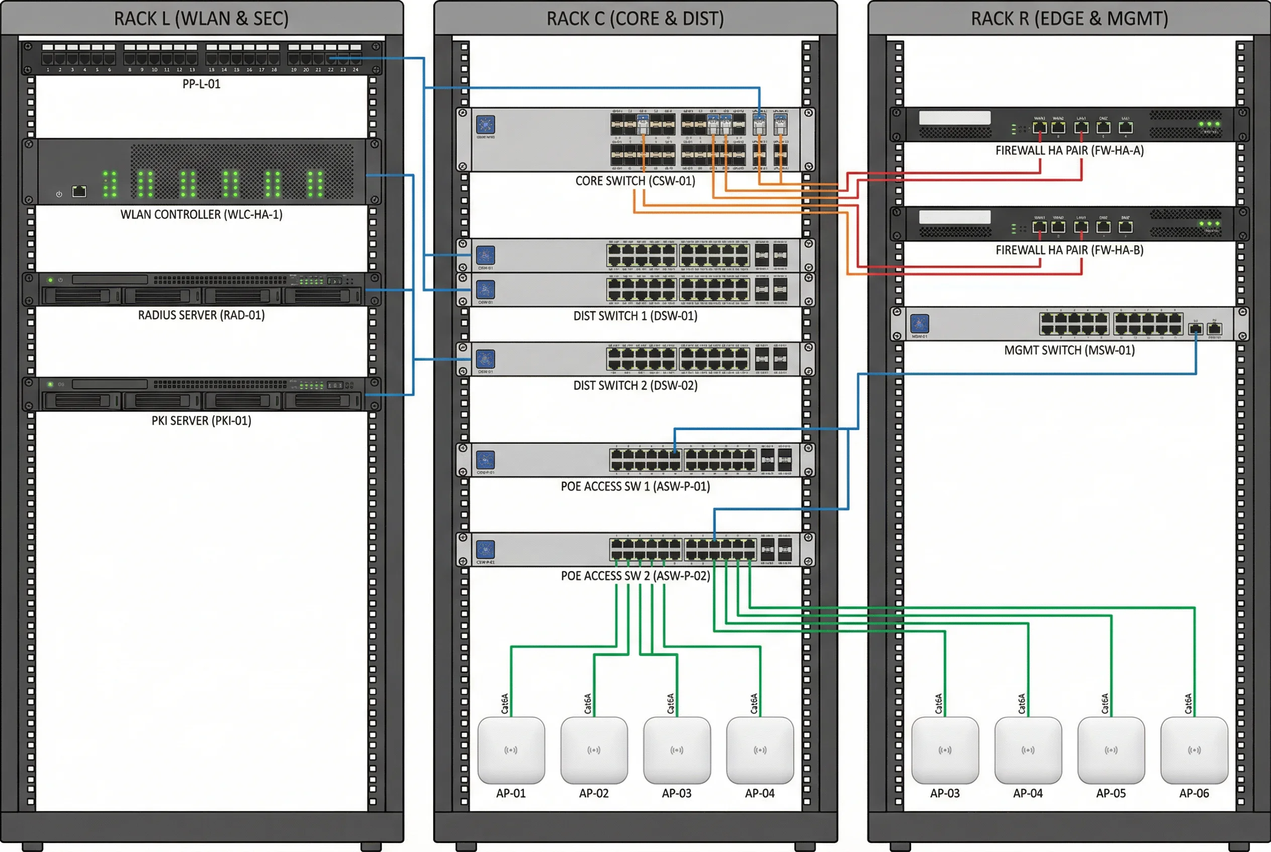
| Cable Color | Connection Type | Media | Speed |
|---|---|---|---|
| Blue | Management (SNMP, SSH, Syslog) | Cat6A RJ45 | 1GbE |
| Orange | Inter-rack uplinks (Core ↔ Distribution) | LC-LC OM4 Fiber | 10GbE SFP+ |
| Green | AP downlinks (PoE Switch → APs) | Cat6A RJ45 | 1GbE PoE+ |
| Red | WAN and firewall external links | Cat6A RJ45 / SFP+ | 1–10GbE |